Mechanical CAD 2 is the next step up from CAD 1. In this class we work on more advanced Mechanical Drafting, including working drawings and isometrics. CAD 2 will build upon the Mechanical Drafting skills learned in CAD 1 by including more complex dimensioning and detailed views. In the second half of Mechanical CAD 2, we will be working on the computer with AutoCAD to improve our workflow and efficiency. The main goal of improving AutoCAD skills is not only to improve quality and the complexity of drawings we can complete but the efficiency in which we can complete them. In the Industry, efficiency is key, employers and customers want high quality work put out in little time.

Plate 3 gave us a more detailed drawing then we had previously done. To draw this correctly, I had to have a strong knowledge of what the part was and I had to be able to orbit the object in my head. This plate emphasized the importance of sketching out the object and planning ahead of time. Without planning ahead, I may have missed lines and dimensions.

Similar to Plate 3, Plate 4 required much more layout and planning ahead of time. Also, the last time I used a compass was my freshmen year, so I had to get used to this. My curves were not perfect, however they got better as I went on throughout the drawing. This included many complex details that caused dimensions to be well thought out and planned ahead of time.

Overall the classroom was not overly complicated however it did include many details that couldn't be missed. This took much more time than the previous drawings because I had to do a lot of erasing between the desks. This also include much more complicated dimensioning.

The Tool Makers Vice presented many firsts including our first time using Vellum paper and our first time doing working exploded drawings. This drawing took more attention to detail then all the previous because you have to add threading. Overall this was challenging, but I would not be more confident doing similar drawings.
AutoCAD
AutoCAD is the most popular CAD system, used by many students, engineers, and businesses. This product is created by AutoDesk and compliments its many other products such as Inventor and Fusion 360. AutoCAD is designed mainly for 2D drawing, but is also able to do 3D drawings. At both of my previous jobs, this was the primary program used, as it is the industry standard.


Carbon Fiber Presentation
Cast Aluminum Chessboard Pieces
I was tasked by our Metal Fabrication teacher to design cast aluminum chess pieces. I was given the requirements to design all chess pieces to have a 1.5 in diameter and be able to be 3D printed, and ultimately cast out of aluminum. To be able to do this project successful, I had to observe other sand cast objects and learn more about the sand casting process. I had to include holes for pins to align the pieces when placed in sand and I had to design the objects so they could be pulled from the mold without damaging it. To do this, I had to add a draft or chamfer to the edges of square pieces, eliminate deep contours, and round objects.


Generative Design
Generative Design allows an engineer to optimize a design to reduce weight and increase strength. Using simulated Forces and Loads, aswell as other parameter, I was able to optimize a part, reducing the weight by 60% while not compromising the strength. Reducing the weight of an object allows the company to produce the object at a lower cost. Also the end products that incorporates the piece will be more efficient because it has less unnecessary weight.

OnShape Drawings
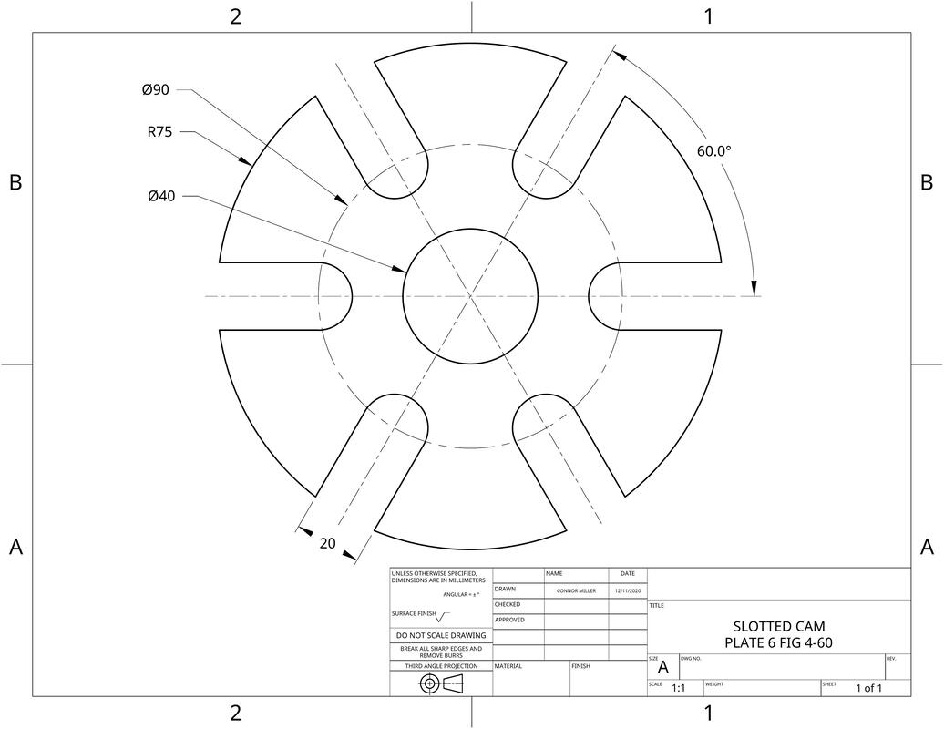
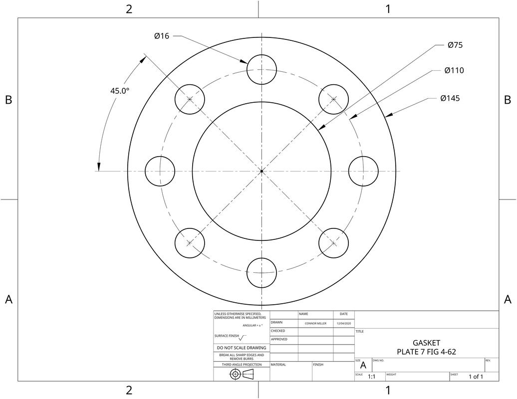
Single View Working Drawings
Single View Workings Drawings are the simplest type of drawings and can only be used in limited situations, the part must be two dimensional with only a thickness needed to be included in a note. Single view drawings can be used to draw flanges, sheet metal stamping, and flywheels.
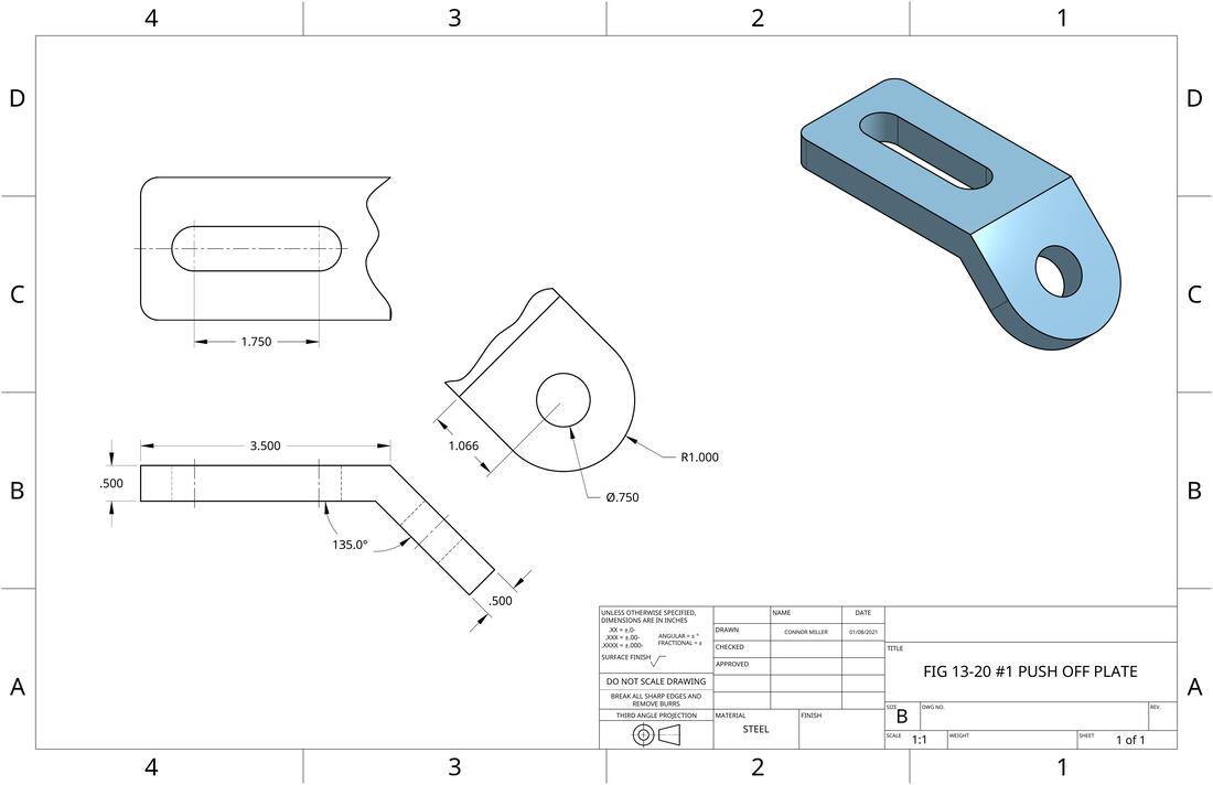
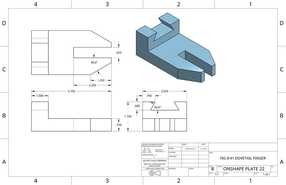
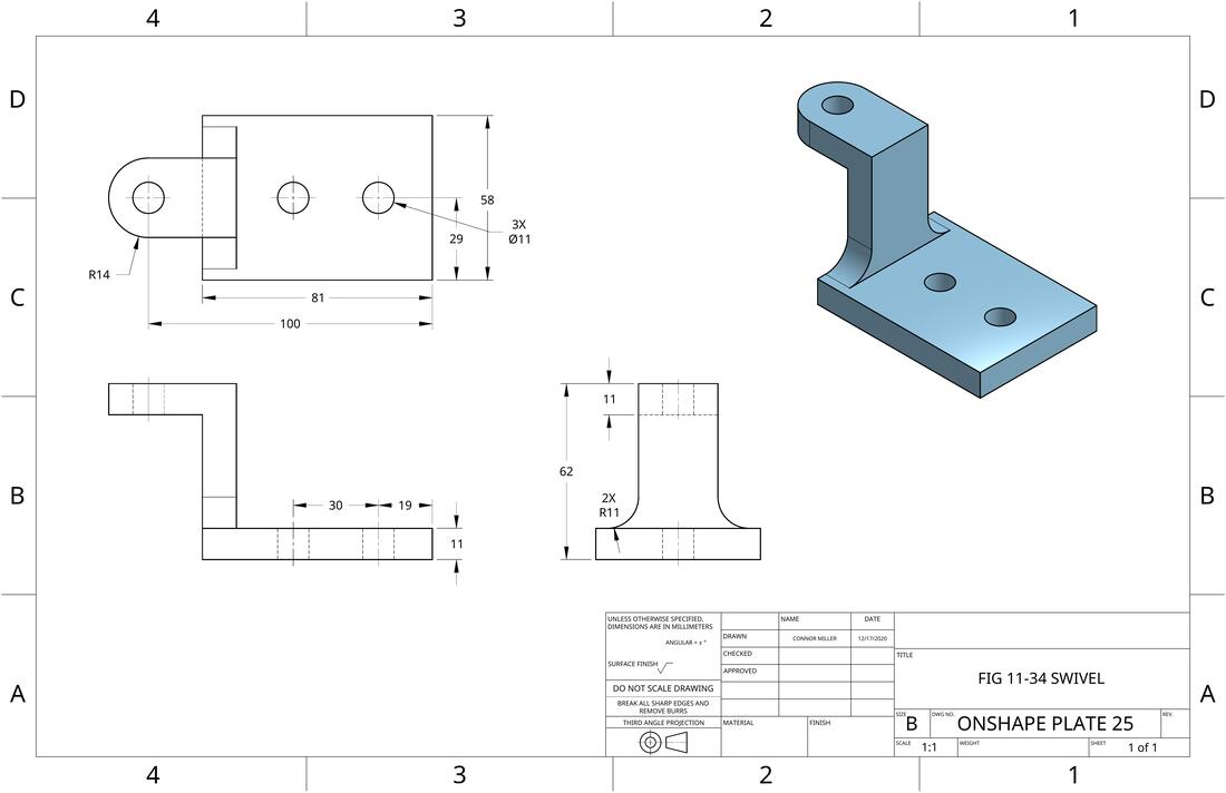
Orthographic and Isometric
Orthograpic Projections with Isometrics allows for a detailed view of a part with accurate dimensions and a good view of the object. These drawings are the most visually pleasing and the easiest to understand, therefore they are very popular in many industries. The Orthographic part of the drawings tie in well to lessons and hand drawings from earlier on in the class.
OnShape Tutorials
The OnShape Tutorials allow us to familiarize with the workflow of Onshape. Programs similar to OnShape (EX: Fusion 360, Inventor, and SolidWorks) are becoming more popular throughout the engineering industry, the collaboration allowed by the programs allows for more efficient workflow and less time fixing errors. Each 3D Modeling program has its own strengths, weaknesses, and quirks, so learning the basics of OnShape was critical to completing more complex drawings.


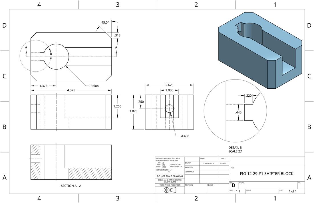
Sections
Sections can be useful in working drawings to show details that would otherwise be hidden. Sections are most commonly used to show details from the inside of an object such as key ways and holes. Sections can be done in full, half, or quarter, depending how much additional detail you would like to show.
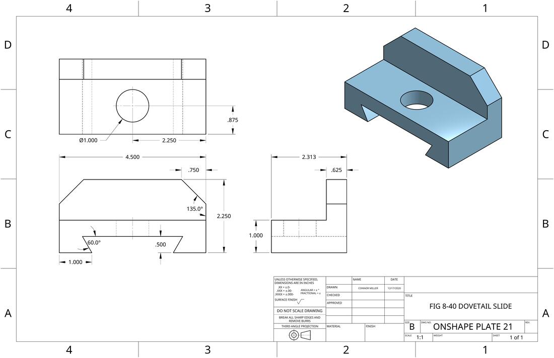
Auxiliaries
Auxiliaries are perfect for working drawings with object faces that are not perpendicular. Non-perpendicular faces are often not well represented by the standard, top, side, and front views. By representing an object with auxiliaries, the manufacturer is able to have a greater understanding of the faces of an object.